Single Board Steckschwein
The single board Steckschwein marks several major milestones in the development of our favourite homebrew computer. The goal has alwas been to integrate the various boards onto one single PCB.
Specifications
65c02-CPU @ 10MHz
512k RAM
32k ROM
Video chip V9958
- Video RAM: 128 KB + 64 KB of expanded VRAM (optional)
- Text modes:
- 80 x 24
- 32 x 24
- Graphics Resolutions:
- 512 x 212 (4 or 16 colors out of 512)
- 256 x 212 (16, 256, 12499 or 19268 colors)
- Sprites: 32 (max 8 per horizontal line)
- Scroll registers
Sound chip YM3812 (OPL2)
- 9 voices
- 2 oscillators (operators) per voice
- 4 waveforms (sine, half-sine, absolute sine, pseudo-sawtooth) per operator
rs232 via UART 16550
SPI used as main peripheral bus for:
- sd-card based mass storage
- PS/2-peripheral controller (keyboard, mouse) (ATmega8)
- RTC (Maxim DS1306)
Memory Map
For a detailed description on how our banking scheme works, see this post and also the slides from our talk at CVFe 22.0.
512k RAM organized in pages 16k each
| Slot | Start | End |
|---|---|---|
| 0 | $0000 | $3fff |
| 1 | $4000 | $7fff |
| 2 | $8000 | $bfff |
| 3 | $c000 | $ffff |
Slot 0 is special, since it also contains the zero page, the stack (as given by the 65C02’s design) and also the IO-area.
| Address | Description |
|---|---|
| $0000-$00ff | Zeropage |
| $0100-$01ff | Stack |
| $0200-$02ff | IO-Area |
| $0300-$3fff | RAM |
The IO-area consists of 16 byte areas for the peripheral devices to be mapped in and also 4 internal registers to control the memory mapping.
| Address | Device |
|---|---|
| $0200 | UART |
| $0210 | VIA |
| $0220 | VDP |
| $0230 | banking register slot 0 |
| $0231 | banking register slot 1 |
| $0232 | banking register slot 2 |
| $0233 | banking register slot 3 |
| $0240 | OPL |
| $0250 | Expansion Slot 0 |
| $0260 | Expansion Slot 1 |
| $0270 | reserved |
The four “banking registers” are used to select the memory page to be mapped into which slot. Writing 0 into the banking register for slot 0 ($0230) will map the first 16k of the 512k into slot 0.
Pinouts
Connectors on the Steckschwein are more or less standard like PS/2, RS232, s-video. RGB is “inspired” by the NeoGeo Console, who used a standard 8pin DIN-Type connector for RGB, Composite Video and Audio.
User Port and the espansion slots have custom pinouts, of course.
S-Video
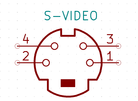
| Pin | Description |
|---|---|
| 1 | Luminance GND |
| 2 | Chrominance GND |
| 3 | Luminance |
| 4 | Chrominance |
RGB
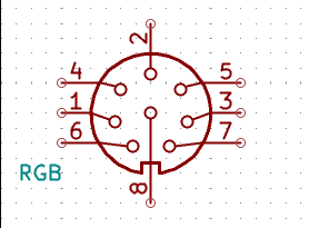
| Pin | Description |
|---|---|
| 1 | Audio |
| 2 | GND |
| 3 | Composite / Sync |
| 4 | 5V |
| 5 | Green |
| 6 | Red |
| 7 | Composite / Sync |
| 8 | Blue |
Expansion Slots
| Pin | Description |
|---|---|
| 1 | D0 |
| 2 | A9 |
| 3 | D1 |
| 4 | A1 |
| 5 | D2 |
| 6 | A2 |
| 7 | D3 |
| 8 | A3 |
| 9 | D4 |
| 10 | RW |
| 11 | D5 |
| 12 | WE |
| 13 | D6 |
| 14 | OE |
| 15 | D7 |
| 16 | CS |
| 17 | IRQ |
| 18 | NMI |
| 19 | RDY |
| 20 | PHI2 |
| 21 | RESET |
| 22 | RESET_TRIG |
| 23 | 5V |
| 24 | GND |
User Port
| Pin | Description |
|---|---|
| 1 | VIA PA0 |
| 2 | VIA PA1 |
| 3 | VIA PA2 |
| 4 | VIA PA3 |
| 5 | VIA PA4 |
| 6 | VIA PA5 |
| 7 | VIA PA6 |
| 8 | VIA PA7 |
| 9 | GND |
| 10 | 5V |
| 11 | N.C. (key) |
| 12 | N.C. (key) |
| 13 | RESET |
| 14 | IRQ |
| 15 | VIA CA2 |
| 16 | VIA CA1 |
JTAG
This connector is used to program the CPLD
| Pin | Description |
|---|---|
| 1 | TMS |
| 2 | TDI |
| 3 | TDO |
| 4 | TCK |
| 5 | GND |
| 6 | 5V |